Outer envelope
The most important advantage of the KB-BLOK systém is the plaster-free and maintenance-free finish of the building façade.
Gaps between the building blocks are jointed in the course of the walling with the KB-BLOK Special Walling Compound or MC 10 cement mortar.
Our current product range offers four options of the surface finish, eight basic colour tones and special colour tones designed for building façades.
This range and possible combinations offer the architect essentially limitless options for designing the building exterior.
The outer envelope masonry is linked to the internal load-bearing wall with clamps (anchors) made of stainless or galvanised steel, inserted in the horizontal joints during the walling. According to structural regulations, at least 5-7 pieces per square metre of visible surface are used. The prescription is 3 per metre length at the ring beam level and near window and door openings.
Any coarse (jointed) masonry is more demanding in terms of workmanship. In the KB-BLOK systém, this execution is even more difficult if elements are cut to size; therefore, it is absolutely essential to pay maximum attention to the façade design already in the architectural design stage.
When building the outer envelope using building blocks with a modular width of 100 mm, the corners are mostly built using KB 5‑11 B (corner split) blocks. However, if you use the less suitable option with KB 3-11 B (bevel-end 45°), it is necessary to take into account the change of modules at corners. The modular length changes to 420 mm here. This change has to be included in the calculation of the external façade dimensions.
The execution project design should design drawings of compositions of each layer of the façade walling, with a specification of the elements.
Generally speaking, KB-BLOK has a counter-value for the wide range of artistic options for the architectural design and surface durability in the form of precision design preparation and adherence to modular coordinations.
Compositions
The building envelope structures have a determining influence on the thermal comfort, indoor microclimate and degree of operating energy intensity.
Due to the low thermal resistance of the building blocks themselves (KB 1-20 A has R=0.197 and KB 1-15 A has R=0.166 m²kW-1), it is essential to choose a composite envelope design, where two basic types are distinguished: contact and contactless. The difference is whether the system includes an air gap or not.
In the contactless composite envelope, the air gap has to be connected to the external environment by holes with an effective cross-section area equal to 2.5‰ of the wall surface. The position of the thermal insulation has to be reliably fixated to prevent any change in the cross-section of the ventilated air gap.
For maximum utility of the service of masonry materials, it is necessary to choose high-quality thermal insulation and anchoring elements and pay attention to flawless execution.
The chapter Thermal technical properties of composite systems quotes some examples of façade masonry compositions tested for the KB-BLOK construction system.
The KB-BLOK construction system ideally meets thermal insulation requirements for buildings. The "composite" separates load-bearing and insulation layers of buildings; there are no cold bridges, and thermal resistance of the building structure can be calculated exactly, dew points determined and, thus, life of the building prolonged.
Another advantage is heat accumulation in the internal concrete walls. This accumulation considerably contributes to a balanced interior climate even during large temperature oscillations.
Ventilation of double-envelope compositions with an air layer
The ventilated air layer should ensure a favourable moisture regime in the composition and enable uses of outer wall structures at higher indoor humidity levels. Its primary functions are:
- removal of water vapour condensation from the wall
- reduction to risk of defects, including laitance
- drainage of water seeped into the wall structure
- drainage of moisture built into the wall structure
- ability to level tolerances during walling
The coordination thickness of the air gap in KB-BLOK systém walls is 50 mm. Its manufacturing design thickness has to be at least 40 mm, and during execution of construction works shall not fall under 30 mm at any place. The air gap has to be vertically continuous.
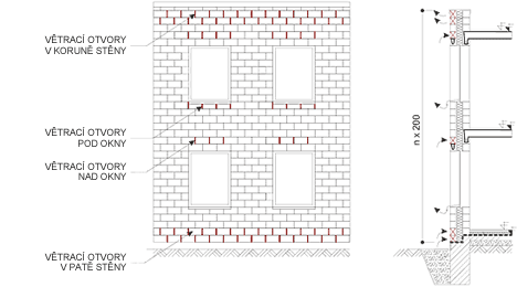
Holes for intake and discharge of air are designed for normal humidity of the internal environment with a cross-section area about 0.4% of the visual surface of the façade, after subtraction of the window and door areas. Ventilation holes are placed at the foot (lowest level) and crown (highest level) of the façade, as well as below and above windows and doors, and as necessary, also below and above the outer layer fastening level, always to produce a vertically continuous air gap without any unventilated pockets and hollows.
The bottom intake holes at the bottom of the air gap have to be at least 150 mm above the adjacent ground with a view to the risk of snow covering them.
Air intake and discharge holes can be made, for example, by leaving out mortar in the contact joints between KB-BLOK building blocks of the outer envelope. In such cases, it is sometimes necessary to make ventilation holes in more rows above each other, namely for the reason of sufficient capacity of ventilation, or in places with the risk of clogging of the lower row, e.g., near the bottom of the air layer.
It is very efficient to provide air intake and discharge for the air layer with continuous slits, e.g., under metal-plating of the parapet and window sills. Ventilation through continuous gaps ensures even air flow and reduces the risk of unventilated pockets.
If necessary, the ventilation holes can be made by leaving out an entire KB-BLOK building block and replacing it with a ventilation grate of the same size. This option has to be assessed in terms of structural analysis.
Holes or slots with one dimension larger than 10 mm are recommended to be covered by grates of the same size. This option has to be assessed in terms of structural analysis.
Ventilation holes may also serve rainwater drainage from the air gap.
The moisture conditions in the designed ventilated air gap always have to be assessed by a calculation under ČSN 730540:94.


